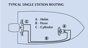
Measure hose routing path from wheel center line to engine connection, as follows:
A = Center line of wheel to gunwale (or deck, if routed downward),
B = Dash to transom,
C = Gunwale to centerline of cable connection at centered tiller.
Most cylinders move with the engine/rudder; enough slack must be left in hoses/tubing to prevent sharp bends (less than 3” radius) and/or kinking.
Where rigid tubing is used, flexible hoses must be installed between tubing and cylinder, to allow cylinder articulation.
For Most Cylinders, add A, B & C + 24”, round up to next even foot. Order that length hose kit, or twice that length in tubing.
Hose routings (such as those found on pontoon boats) may vary from this drawing. Confirm length by laying a garden hose along cable path and measure run from wheel to engine connection point.
Typical Single Station Routing
A single, front-mount outboard cylinder system is shown in this diagram.


